Commercial buildings in city centres tend to be relatively tall 6 to 12 storeys is a typical city centre project because of the high cost of land and the confinement of adjacent buildings and utilities. Planning requirements have a strong impact on the building form and its architecture, and in many parts of the country, it is a planning objective that commercial buildings are required to generate a proportion of their on-site energy use from renewable sources , e.
An important aspect of many modern commercial building developments is the need for retail space at ground floor, office space above, and in many cases, below ground car parking. This can lead to complexity in the alignment of planning grids from floor to floor. A common solution is to create a transfer structure at ground or first floor levels to optimise the space use above and below. The sub-structure of city centre projects tends to be complex because of the high loads that are supported, the need to avoid affecting the foundations of neighbouring buildings, and to avoid obstructions and services in the ground.
Piled foundations below basement level are most commonly used and the piles are placed in a group of typically 3 or 4 below a pile cap. There are various techniques to form basements including temporary sheet pile walls supported by steel H sections and contiguous bored pile walls.
Services also tend to be complex and some form of combined structure-services zone is considered in the building design. Vertical services are routed at discrete points on plan and distributed horizontally through the building. Long-span solutions are commonly used in this sector in order to optimise the internal space use. In London, a number of major towers have taken steel to new frontiers. Two of these are the Swiss Re building and the Broadgate Tower.
The steel structure was therefore a key part of the architectural concept. This project was completed without disrupting the day to day operation of this major London railway hub. The requirements for access to the upper levels of tall buildings and for overall stability mean that the core area is a high proportion of the plan area and is generally located centrally on plan. The office space wraps around the core, and from a functional point of view, this space should be as flexible as possible. The main beams therefore radiate from the core and are supported on perimeter columns.
The provision of natural lighting tends to mean that the width of the office space is limited to about 15m. Services emanate from the core and are distributed through openings in the structure. The nature of the construction is that the core is generally in slip formed reinforced concrete. The core construction progresses a few floors above the steel construction, which is faster and so its progress is limited by the construction of the core.
Larger commercial buildings are often designed around an atrium, which provides natural lighting and circulation space for the offices around it. The area of the building on plan tends to be large over 1,m 2 per floor and the atrium is often located centrally, or may form part of an extended entrance area. The atrium is designed as part of the whole building energy and lighting strategy, and also provides the safe means of escape in fire; therefore smoke control in the atrium is a crucial part of the design solution.
For a building layout point of view, the commercial space is typically 15 to 18m wide around the atrium and the cores are located at positions dictated by means of escape in fire. Generally, a minimum of two cores, and often as many as four separate cores are required on plan in buildings with atria. The simplified plan form of an office building with a central atrium is shown. The service routes from the cores can be relatively long, which means that the duct sizes can be large when distributed from the core. In this area, the use of shorter span beams with large rectangular openings may be more practical.
The steel elements used in the atrium are generally in the form of hollow sections and tension ties, which are often designed architecturally to emphasise the high quality of the public space that is created. Tower Place in London combines a wide range of steel members, including hollow sections in the 6 storey high entrance atrium, as shown. These mixed use buildings pose particular questions in terms of the building layout in terms of:. Mixed use buildings can be designed so that the column grid is compatible with the different uses.
For buildings over car parking , the column layout has to be compatible with the space below. A clear span of 17m is therefore the optimum for both the car parking and commercial space, and this can be achieved in steel construction. Shallow floor systems , such as Ultra Shallow Floor Beams USFB , may be used for basement car parking and this has the potential to reduce the basement depth. Alternatively in residential buildings over commercial or retail areas , a steel transfer structure may be designed above the office or retail space , so that the residential space may be configured optimally.
The transfer structure is designed to support the weight of the building above and so the use of a lightweight steel structure above leads to direct benefits in terms of the size and complexity of the transfer structure. This is an important market for steel construction. In-out-of-town or suburban areas, commercial buildings are often smaller typically 2 to 4 storeys than in city centres and are less constrained by the buildings around them. In this type of building, natural ventilation is often preferred to air—conditioning for environmental and economic reasons.
Therefore the depth of the floor plate is limited to around Conventionally, this is achieved using an off-centre line of columns at 7. A simplified plan form is shown. Many buildings on science parks or out-of-town-areas are designed for a range of space uses and often the energy efficiency strategy is based on effective shading and air movement to improve ventilation and to avoid over-heating.
Foundations tend to be simpler than in city centre projects. Solutions such as pad footings under columns and basements are not common unless used to house services plant. In that case, the basement does not usually extend over the whole plan area of the building. Braced frames , Continuous frames , Composite construction , Floor systems , Long-span beams. The majority of structural systems used in office construction are braced by one of two methods;.
The choice of this system depends on the form and scale of the buildings. In most buildings up to 6 storeys high, steel bracing is preferred, although its location is strongly influenced by the layout of the building. V or K bracing using tubular sections is often preferred as it is more compact and can be arranged around windows and doors in some cases.
X flat bracing is preferred for use in brickwork as it can be located in the cavity between the leaves of the brickwork.
For taller buildings, concrete cores are more efficient and they can either be constructed floor by floor using conventional formwork, or slip-formed continuously. The relative economics is dictated by speed of construction, and slip forming is often used on tall buildings see Commercial buildings with atria. Steel plated or composite cores are also used where there is need to minimise the space occupied by the core and where it can be constructed in parallel with the steel framework. The structural design of the steel frame is therefore based on the use of simple shear resisting connections for both the beam to column and beam to beam connections.
Continuous frames achieve continuity of the beams either by design of the steel structure so that they are multi-span, or by use of moment-resisting connections.
Popular Pages
In the Palestra building , the primary beams were arranged in pairs either side of the tubular columns , and the beams were continuous across the building, being spliced only at the quarter span positions from the internal columns where bending moment were low. In that way, the beams are stiffer due to their continuity than the equivalent simply supported beam and so that depth can be reduced.
A view of the building during construction is shown. In buildings up to four storeys in height, it may be economic to design the steel structure as a sway frame to resist lateral loads applied to the building. The connections between the beams and the columns are made moment-resisting by use of extended end plate connections. The columns may be heavier than in simply supported design, but the beams can be lighter, and bracing is eliminated. This may be advantageous in low-rise buildings with highly glazed facades.
Composite construction consists of downstand I-section steel beams with shear connectors studs welded to the top flange to enable the beam to act compositely with an in-situ composite floor slab. The composite slab comprises profiled decking of various shapes that span 3m to 4m between secondary beams. Floor slabs are typically mm to mm deep, depending on the deck height. The shear connectors are normally site welded through the steel decking which then supports the wet weight of the concrete and construction loading and later acts compositely with the concrete. The secondary beams in the floor grid support the composite slab and are supported by primary beams.
Therefore, 6m x 9m and 7. Heating and ventilation units can be positioned between beams , but ducts will generally pass below downstand beams. Typically, for a 7. This floor depth may reduce to mm in the case without air conditioning services. A typical example of a composite beam with service routing is shown. Long span composite beams are often designed with large web openings to facilitate integration of services , as shown. In long-span construction, grids are generally arranged so that the long span secondary beams are supported by shorter span primary beams.
It may be economic to design long span primary beams that support shorter span secondary beams , when considering the use of cellular and fabricated sections. Web stiffeners may be required around large openings. Elongated or rectangular openings should be located in areas of low shear, e. Isolated openings can be reinforced by horizontal stiffeners, as shown, which increases their resistance to shear by local bending around the openings Vierendeel bending. Stiffened large web opening in a steel beam. Services located through web openings in the beams.
Cellular beams are beams with openings regular spacing along their length. The beams are made by cutting and re welding hot rolled steel sections. The full range of hot rolled steel section sizes is available from which to choose the sizes of the top and bottom chords. For composite design, the top chord is generally chosen as a lighter section than the bottom chord. Cellular beams are generally arranged as long span secondary beams , supporting the floor slab directly, as shown.
Fabricated beams are made from three steel plates whose sizes can be selected for the particular loading case. Openings for services can be cut into the web, and the sizes of the openings can be designed depending on the forces acting at a point in the span. An example of fabricated beams with circular elongated-circular and rectangular openings is shown. One of the advantages of the use of fabricated beams is that they can be designed to support relatively heavy loads when used as long spanning primary beams.
Tapered beams can be designed so that the depth of the beam is tailored to broadly match the bending moment applied to it. In this way, the depth of the tapered section is normally in the form of a single linear variation from mid-span to the supports, and the minimum depth at the supports is sized only to provide the required shear resistance. Relatively wide zones for services are provided near to the supports. An example of tapered beams is shown.
Shallow floor beams are typically asymmetric steel beams with a wider bottom than top flange, which enables the slab to sit on the upper surface of the bottom flange with adequate bearing, rather than the upper surface of the top flange as found with downstand beams. The floor slab may be in the form of a precast concrete slab or a composite slab with metal decking either shallow or deep decking may be used.
The USFB is manufactured from standard rolled sections , and is available in increments of 1mm depth. USFBs can economically span up to 10m with structural depths that compare very favourably with R. As such, they are popular in many sectors including multi-storey office buildings. The three generic forms of flooring systems which are most commonly used in steel framed office buildings are:. The generic shallow deck profiles used in composite floors are illustrated. During the construction stage, and prior to composite action of the decking and concrete being fully achieved in the normal stage, the decking alone will need to support the load due to wet concrete and construction live loads.
Pattern loading due to the construction sequence should also be considered during the construction stage. During construction, propping to the decking may allow longer spans to be achieved in the normal stage. Propping may be seen as impacting on access and programme and to whether or not to prop the decking should be discussed early in the design process. Props should be left in place until the concrete has reached its design strength.
Modern composite slabs contain re-entrant portions which facilitate attachment of wires for suspended services and ceiling. Trapezoidal profiles are based on a mm rib spacing, and often the cross-section is highly stiffened to improve its bending and composite properties. Reinforcement in the slab provides up to minutes fire resistance , but for longer periods of fire resistance which are unusual in the UK , reinforcing bars may be placed in the deck ribs.
Steel decking is installed by craning onto the primary steelwork in bundles and usually man-handling into position. A fall arrest system is installed immediately after the steelwork is erected and before the decking is placed. Completed and decked floors may be used as a safe working platform for subsequent installation of steelwork. For this reason, the upper floor in any group of floors usually three floor levels is often concreted first.
The deep decking is supported on end diaphragms which provide stability to the web of the decking and also prevents loss of concrete when it is poured on the decking. Reinforcing bars of 12 to 20mm are placed in the deck ribs, mainly for fire resistance purposes, and mesh reinforcement is placed in the topping. Un-propped spans of up to 6m can be achieved. Shallow floor systems are used in many sectors and often in mixed-use buildings and in basements or car parks to multi-storey buildings where minimising of the floor depth has economic value.
Precast concrete slabs are proprietary products that are manufactured in standard depths and widths. They are pre-stressed to increase their spanning capabilities and stiffness which also means that they have some negative curvature when unloaded. Hollow-core slabs have regular circular openings and in some cases, elongated openings along their length to reduce their weight.
Precast slabs are widely used in smaller offices, but less so in large building projects. They are also used in Shallow floor systems. Cost of structural steelwork , Cost planning through design stages , Cost comparison studies , Operational carbon , Thermal mass , Target Zero , Service integration , Fire and steel construction , Acoustics , Floor vibrations , Fabrication , Construction. Procurement in the commercial building sector is often different from other sectors, depending on whether the building is a speculative development, or is intended for a single client.
This two stage process means that the hand-over between architects and contractors in the two stages has to be carefully managed to avoid division of responsibilities. The second stage fit-out can involve as little as internal partitioning and decoration, but can include complex installation of services and specialist IT systems.
For single clients, the procurement process is more straightforward in that the client brief will define the functional and spatial requirements, and then the whole construction process falls under one contract. There are three generic contractual systems that may be used for commercial buildings depending on their scale and the type of client:. A recent important innovation is that of Building Information Management BIM systems in which the design team, contractor and specialist suppliers share in a common design and drawing system so that interface and scheduling problems are minimised.
The BIM system is generally managed and controlled by the main contractor and requires an early involvement of specialist suppliers in the design process. Client requirements have an important effect on the planning of modern commercial buildings, and influence how the benefits of steel construction may be achieved in practice. These requirements may be defined by the physical aspects of the building, floor loadings, and the building services and fire safety strategy. The British Council for Offices has produced specifications and guidance on the design parameters that are relevant to this sector.
The floor to floor zone is a key design parameter, which is influenced by planning requirements, such as overall building height, natural lighting, aesthetics , and other aspects. The economics of most commercial buildings is that the client or developer expects to re-coup the investment in 10 to 15 years, and so there is a premium for early completion and future adaptability to meet a range of functional requirements. It is estimated that the total cost of running a building during a 60 year design life may be 3 to 5 times the initial construction cost. Major components of the longer term operational costs include:.
The energy performance of office buildings is a major factor in modern design because lighting, heating and cooling are major users of energy , generally in the form of electricity. Under Part L of the Building Regulations, modern commercial building projects are required to meet increasingly tough operation carbon emissions targets. Also, since , all commercial properties are also required to have an Energy Performance Certificate.
Energy performance therefore strongly influences, and can impose restrictions on, how the commercial buildings are designed. The as-built cost of a modern commercial building which may involve office, retail, and public space varies greatly depending on its complexity and location. Specific guidance on the cost planning of multi-storey commercial buildings is available. Preliminaries represent the costs of the site management and on-site facilities, including hire of cranes, storage space and equipment. The results of a recent independent cost comparison study of multi-storey commercial buildings is also available.
Access Denied
Composite construction has become the dominant form of construction in the commercial building sector because it provides long span , stiff floors and because it is a rapid form of construction. The steel erection programme is dependent on the number of tower cranes employed and use of long span beams requires fewer albeit heavier components, and therefore speeds up the whole process. Bundles of decking are placed on the steel beams , as shown.
The construction programme for a typical steel framed office building of 6 storeys height and about m 2 floor are as shown. The placing of decking follows the steelwork installation and the concreting operation can take place one floor below. Through deck welding of the shear connectors also speeds up the process.
Having concreted the floor without any temporary propping, the next day it acts as working platform for following trades such as servicing, and placement of infill walling , whilst the upper floors are being installed. This can lead to considerable cost savings. The steelwork package is a single point of procurement and often includes decking and through deck welding of shear connectors , and in some cases, concreting.
This ensures that cladding and services are integrated with respect to the steelwork design. In city centres, major services and underground works, such as tunnels, often influence the chosen solution. Poor ground conditions tend to require a lightweight solution involving fewer foundations. This often necessitates long span for the superstructure.
A confined site can place constraints on choice of the structural scheme, for example the size of the elements that can be delivered and erected. Composite floors are often preferred in these cases. Multi-storey structures are often erected using a tower crane. The number of cranes required on a project is influenced by:. Fewer pieces to install, or use of more cranes, will reduce the construction programme. Smaller inner city sites are often served by a single tower crane that is used by all trades. These competing demands can slow overall progress of the steelwork erection.
For larger projects, it is an important requirement to enable other trades to commence their activities as the steelwork installation progresses. As an indication, an installation rate of between 20 and 30 pieces of steel per day is reasonable for most commercial building projects. For average weights of the components, this equates to approximately 10 to 12 tonnes of steel per day.
Concrete in modern steel-framed buildings is placed by pump using concrete mixes designed for this purpose.
Framing Square Basics
Concreting rates of over 2,m 2 per day are possible approximately m 3 of concrete. This means that a whole floor can be concreted without construction joints.
An accurate concrete level is achieved in un-propped composite construction and the light steel edge trim ensures that the level is maintained at the facades and at large openings. Where required, construction joints are generally made along the lines of the beams. From the top edge of this mark measure along the top edge of rafter inches 13' 5" and make another pencil mark.
Place the framing square on this mark as before and draw another plumb cut line. This line represents the outside of the building, add tail cut as needed. Next step is to mark seat cut for birdsmouth, then shorten top plumb cut by half the thickness of ridge board. Determine span, determine run, determine pitch, determine length, layout rafter, cut, and test. This method is by far the fastest, easiest, and most accurate of these three methods of marking and cutting common rafters. Anyone who does this kind of carpentry work really should learn how to use a Construction Master calculator.
I have been using one for over 15 years and wonder how I ever got along without it. If you read the beginning of this page you found the reference to someone else needing it worse than me. My Carhart jacket was stolen from the local watering hole and my calculator was in the pocket. Maybe I should have left before the third beer, we all know how that goes. Anyway the steps are to follow. Determine overall span of rafters. Determine run of rafters. All four of these steps are much easier with a construction calculator.
All you really need to know is the span and pitch to cut the common rafters. After just a few times of doing it this way you should be comfortable with the calculator. Here are a few of the numbers the calculator stores just from these two pieces of information. You still have to use the framing square to lay out the rafter cuts, however there is no need to shorten it up for the ridge board since I took it out in the very beginning.
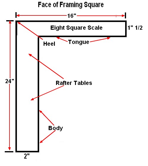
There is no other tool available today that holds the answers to common roof framing problems than the framing square. It would be useless for me to go on and on about the many virtues of the steel square. I will only talk to you about the little numbers on the framing square that you will need for conventional roof framing. Many of the solutions and numbers are outdated and seldom used by modern carpenters.
There are two main parts to the square, the body and the tongue. The body is the 2" wide 2' long blade on the square. The body is normally used to mark the level or horizontal cuts on the rafter. The body and tongue intersect at the heel on the outside edge of the square. There is also front and back to the square which I could write a whole chapter and probably only confuse you and myself. For this reason I have included two images to better explain the front and back.
The most important set of numbers on the framing square are the rafter tables. These are located on the face side of the body. The first four rows of numbers are the most important and the only ones I will cover here. Length of common rafters per foot run. This row represents how long a common rafter is per foot of run. To find the number needed look under the number of the pitch of the roof you are working on. For example if you look under the 6" mark on the outside edge of the body you should find Length of hip or valley per foot run.
This row represents the length of a hip or valley rafter per foot run. Difference in length of jacks at 16" and 24" centers. There is actually one row each for 16 and 24" centers. These two rows represent how much longer or shorter the next jack rafter is than the previous one. In other words if you need one longer, add the number from the column to get the next one. If you are working your way downhill subtract the number.

You might find the brace measurement tool handy if you build decks or need a permanent, good looking brace for any reason. If you look closely at the tongue on the back side of the framing square you will see two small numbers stacked one on top of the other with a larger single number just to the right of this smaller set of numbers.
Gilbert Townsend (Author of Carpentry Woodworking Book Framing Roofs)
The first set of numbers is 24 stacked on each other followed closely by the number In other words if you need a brace for a porch or deck set at a 45 degree angle, measure 2 feet away from the post and 2 feet down the post and the length of your brace should be Always use outside edge of framing square when possible to avoid confusion. Get a good framing square, the Wal-Mart cheapie will not do the job. Use stair buttons to speed up the framing square step off method and reduce the chance of mistakes. Use the two foot step off technique if possible. To accomplish this task, just double all measurements on the framing square.
Framing Square to Homepage. Common Rafters and Framing Square Basics The framing square is one of the most useful and versatile tools in carpentry. Framing Square with Regular Calculator This method of laying out common rafters is much faster, more accurate, and easier than stepping them off with a framing square.